



Understand the features before choosing the machine
Industrial Vacuum Parts & Terminology Guide
Industrial vacuum specifications can look like a list of disconnected terms: HEPA, M-Class, PTFE, JetClean, Longopac, single-phase, three-phase, side-channel blower, tangential inlet, and dozens more.
Those terms do not all describe the same part of the vacuum. Some describe the suction source. Others describe the primary filter, final filter, filter-cleaning method, collection system, discharge method, or safety-related configuration. Understanding those differences makes it easier to compare equipment and avoid selecting a vacuum that is poorly matched to the material or duty cycle.
Start with the material or cleanup problem
Find the Right Industrial Vacuum Starting Point
You do not need to understand every industrial vacuum term before narrowing the options. Start with the material, cleanup process, operating time, and collection method. The paths below lead to the most relevant Depureco category for further review.
Fine Dust or Powders
Start with filter area, filter media, filter cleaning, pre-separation and the required collection or disposal method.
HEPA or Controlled Bagging
Review final filtration, primary-filter protection, Longopac collection and how the material will be sealed and removed.
Liquids or Mixed Debris
Start with liquid compatibility, float protection, solids content, tank capacity and the required discharge method.
Coolant, Chips or Swarf
Review chip geometry, coolant volume, sludge content, separation requirements and whether recovered fluid will be reused.
Extended or Heavy-Duty Use
Start with duty cycle, three-phase power, blower type, filter area, hose distance and collection capacity.
Combustible or Hazardous Dust
Begin with the material hazard, area classification, static-control path and documented equipment configuration.
Look beyond horsepower and filter labels
How to Read an Industrial Vacuum Specification
An industrial vacuum specification should be read as a complete system. The suction source, filtration, filter cleaning, material separation, collection method, and operating environment all affect whether the equipment will work for the application.
Use the five layers below to compare vacuum configurations and identify which questions remain unanswered before ordering.
Power & Suction Source
Identify how the vacuum generates suction and which utility the facility must provide.
- Single-phase bypass motors
- Three-phase blowers
- Roots blowers
- Compressed-air systems
Filtration
Review the primary filter, optional final filtration and how the filtration system fits the material.
- Filter class
- Filter media
- Filter geometry
- Filter surface area
Filter Cleaning
Determine how accumulated dust is removed from the working filter and how often cleaning is required.
- Manual shaker
- JetClean
- Pneumatic cleaning
- Reverse pulse
Separation & Collection
Review how material is separated from airflow and how it will be contained, emptied or recovered.
- Tangential inlet
- Pre-separator
- Bin, drum or hopper
- Longopac or liquid discharge
Material & Environment
Confirm that the complete configuration fits the material, operating conditions and facility requirements.
- Dry, wet or mixed material
- Particle or chip size
- Temperature and volume
- Toxicity, conductivity or combustibility
Match the power platform to the run time
Power, Motors, and Duty Cycle
The power supply does more than determine where an industrial vacuum can be plugged in. It also affects the suction technology, expected operating time, mobility, and type of application the machine can support.
Single-phase, three-phase, and air-powered vacuums can all deliver useful industrial performance. The correct choice depends on how long the vacuum will run, what material it must recover, how far the material must travel, and which utilities are available in the facility.
Single-Phase Industrial Vacuums
Single-phase industrial vacuums commonly use one or more bypass motors and connect to power that is widely available throughout many production and maintenance areas.
They are often selected for mobile cleanup, machine-area cleaning, scheduled housekeeping, and point-of-use dust or debris recovery.
Best for:
Mobile plant cleanup
Intermittent or scheduled cleaning
Fine dust and powders
General manufacturing debris
Properly configured wet and dry applications
Facilities without three-phase power at the pickup point
Multiple independently controlled motors may allow the operator to adjust suction or use only the power needed for the task.
Common mistake: Do not assume every single-phase vacuum is light duty, wet and dry capable, or designed for continuous operation. The exact motor platform and intended duty cycle must be confirmed.
Three-Phase Industrial Vacuums
Three-phase industrial vacuums commonly use side-channel or regenerative blowers designed for longer operating cycles and demanding industrial environments.
They are often paired with larger filters, higher collection capacities, and configurations intended for frequent or extended use.
Best for:
Long or repeated cleaning cycles
High material volume
Production support
Dense or abrasive material
Large filter-area requirements
Fixed or centralized applications
Facilities with compatible three-phase power
Common mistake: Three-phase power does not automatically mean that a vacuum has more usable suction for every material. Airflow, vacuum pressure, hose size, distance, filter loading, and material behavior still determine application performance.
| Selection Factor | Single-Phase | Three-Phase |
|---|---|---|
| Typical use | Mobile, scheduled or point-of-use cleaning | Extended, demanding or fixed industrial use |
| Common suction source | One or more bypass motors | Side-channel or regenerative blower |
| Power availability | More widely available throughout many facilities | Requires compatible plant voltage and three-phase power |
| Operating duty | Often intermittent or scheduled, depending on the model | Generally better suited to longer operating cycles |
| Mobility | Frequently selected for mobile cleanup | Available in mobile, stationary and centralized configurations |
| Collection capacity | Small to medium, depending on configuration | Often paired with larger bins, hoppers or separators |
| Primary deciding factors | Mobility, available power and cleanup frequency | Duty cycle, throughput, hose distance and facility utilities |
Other Motor and Suction Terms
The electrical phase is only one part of the suction system. The motor or blower design helps determine how the vacuum handles operating time, airflow resistance, portability, and demanding material-recovery conditions.
Bypass Motor
A bypass motor uses separate airflow to cool the motor rather than relying only on the process air moving through the vacuum.
Best for- Portable industrial vacuums
- Mobile plant cleanup
- Intermittent or scheduled use
Number of motors, independent controls and intended operating cycle.
Side-Channel Blower
A side-channel or regenerative blower creates suction through a rotating impeller and recirculating side-channel airflow path.
Best for- Three-phase industrial vacuums
- Longer operating cycles
- Mobile or stationary heavy-duty systems
Voltage, frequency, relief protection and required performance.
Roots Blower
A Roots blower is used where an application requires higher transport capability, long distances, bulk recovery or an engineered central system.
Best for- High-power material recovery
- Long piping or hose routes
- Centralized vacuum systems
Material density, transport distance, elevation, pipe sizing and discharge.
Air-Powered Vacuum
An air-powered or pneumatic vacuum uses compressed air rather than an electric suction motor.
Best for- Facilities with sufficient compressed-air capacity
- Selected maintenance or material-handling applications
- Situations where a non-electric suction source is preferred
Air pressure, required air volume, energy use, material and area classification.
Explore Air-Powered Industrial Vacuums- Available voltage
- Electrical phase
- Frequency
- Amperage
- Plug or hardwired connection
- Expected operating time
- Compressed-air capacity
- Hose or piping distance
- Material type and volume
Read performance as a working combination
Airflow, Vacuum Pressure and Performance

Industrial vacuum performance is not represented by one number. Airflow, vacuum pressure, hose diameter, pickup distance, elevation, filter condition, and material behavior all affect how the vacuum performs at the actual pickup point.
Maximum airflow and maximum vacuum pressure are normally measured under different test conditions. The correct system is the one that maintains useful performance after the hose, tool, filter, and material introduce resistance.
CFM and Airflow
CFM, or cubic feet per minute, describes the volume of air moving through the vacuum system.
Airflow is especially important when the application requires the vacuum to capture or carry lightweight material across a larger opening.
Airflow is commonly important for:
- Fine, lightweight dust
- Powders
- Wide floor tools
- Large pickup openings
- Suspended particulate
- Packaging trim
- Lightweight production scrap
Higher airflow does not automatically mean the vacuum will lift dense material through a restricted tool or long hose.
Vacuum Pressure, Depression, and Water Lift
Vacuum pressure describes the system’s ability to overcome resistance. It may be expressed as water lift, inches of water column, inH₂O, millibars, or another pressure unit.
Higher vacuum pressure is often more important when the material is dense, the pickup opening is narrow, or the system must overcome significant hose and elevation losses.
Vacuum pressure is commonly important for:
Dense metal chips
Long or stringy swarf
Sludge
Material packed into corners
Narrow crevice tools
Long hose routes
Vertical lift
Restricted piping or accessories
Vacuum pressure should still be evaluated alongside airflow. A system needs enough air movement to transport the material after it has been lifted.
| Application Condition | Airflow Importance | Vacuum Pressure Importance |
|---|---|---|
| Fine, lightweight powder | High | Medium |
| Wide floor cleaning | High | Medium |
| Dense metal chips | Medium | High |
| Sludge or settled solids | Medium | High |
| Long hose route | High | High |
| Narrow crevice tool | Medium | High |
| Packaging trim or lightweight scrap | High | Medium |
| Large-volume bulk recovery | High | High |
Other Performance Terms to Know
Maximum Vacuum
The highest vacuum pressure the suction unit can generate near a closed or highly restricted condition. It is not the same as the pressure available during normal material transport.
Filter Loading
Dust accumulating on the filter increases resistance and can reduce airflow. Filter area, media and cleaning method affect how quickly this occurs.
Differential Pressure
The pressure difference across the filter. A rising value can indicate that the filter is becoming loaded and may require cleaning or service.
Relief Valve
A protective component that allows additional air into the suction system when airflow becomes restricted. It does not replace correct hose sizing or filter maintenance.
Keep airflow from falling as dust accumulates
Industrial Vacuum Filter-Cleaning Systems
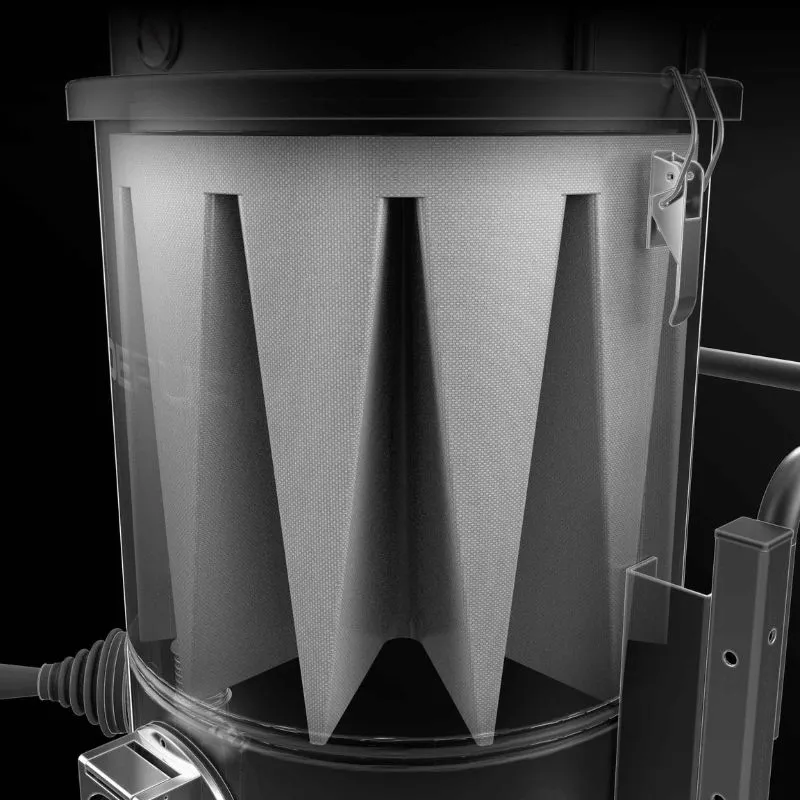
Dust accumulating on the primary filter increases resistance and gradually reduces airflow. A filter-cleaning system helps dislodge that buildup so the vacuum can maintain more consistent pickup performance between maintenance intervals.
The correct cleaning method depends on the dust, operating time, available utilities, and whether the operator can stop collection to complete a cleaning cycle. Manual shakers, JetClean, pneumatic mechanisms, and reverse-pulse systems perform the same general job in different ways.
What Happens as the Filter Loads?
As dust builds on the working filter, air must pass through a thicker layer of collected material. This added resistance can reduce airflow at the hose and tool even when the suction motor or blower is operating normally.
Signs that the working filter may require cleaning include:
Reduced pickup at the tool
Longer cleanup time
Rising differential pressure
Material remaining in the hose
Frequent relief-valve activation
Noticeably weaker airflow after extended collection
Filter cleaning removes part of the accumulated dust cake. It does not replace periodic filter inspection, correct maintenance, or replacement of a damaged or permanently blinded filter.
Manual, JetClean, Pneumatic, and Reverse-Pulse Cleaning
Manual Filter Shaker
A manual shaker mechanically moves or flexes the working filter so accumulated dust falls into the collection chamber.
Best forScheduled cleaning where the operator can briefly stop collection and complete a cleaning cycle.
Main considerationPerformance depends on the operator cleaning the filter regularly and following the correct procedure.
JetClean
JetClean is used on selected Depureco fine-dust vacuums to help dislodge accumulated dust through controlled airflow and pressure differential.
Best forFine dry dust and powders that progressively load the primary working filter.
Main considerationJetClean is a filter-cleaning method. It does not determine HEPA filtration, collection method or hazardous-dust suitability.
Pneumatic Piston Cleaning
A pneumatic mechanism uses compressed air to actuate a piston or mechanical system that shakes or impacts the filter structure.
Best forLarger industrial vacuums that need repeatable cleaning force and have compressed air available.
Main considerationThe required air pressure, volume and connection must be included in the application review.
Reverse-Pulse Cleaning
Reverse-pulse systems send compressed air through the filter in the opposite direction of normal operating airflow.
Best forDust collectors, cartridge systems and high-dust processes where automatic or sequenced cleaning is valuable.
Main considerationThese systems require compressed air, controls and more complex maintenance than a basic manual system.
| Cleaning Method | Utility | Operator Involvement | Typical Fit | Main Limitation |
|---|---|---|---|---|
| Manual shaker | No additional utility | High | Mobile and three-phase industrial vacuums | Depends on operator consistency |
| JetClean | Vacuum pressure differential | Medium | Selected fine-dust mobile vacuums | Requires the correct cleaning procedure |
| Pneumatic piston | Compressed air | Low to medium | Larger industrial vacuum systems | Requires sufficient compressed air |
| Reverse pulse | Compressed air and controls | Low | Dust collectors and engineered cartridge systems | Greater system complexity |
Questions That Determine the Right Cleaning System
Before selecting a filter-cleaning method, confirm:
What exact dust or powder will be collected?
How quickly does it accumulate on the working filter?
Is the material dry, sticky, oily, or moisture-sensitive?
How long will the vacuum run during each cycle?
Can the operator stop pickup to clean the filter?
How frequently can maintenance be performed?
Is compressed air available at the machine?
Is automatic or sequenced cleaning required?
Will the vacuum collect fine dust continuously or only during scheduled cleanup?
Is the application better suited to a mobile vacuum or a dust collector?
Common mistake: Do not select a cleaning system only because it is more automated. The dust, operating cycle, available utilities, and maintenance capability should determine whether the added complexity provides a real advantage.
Differential Pressure and Filter Condition
Differential pressure is the pressure difference measured before and after the filter. As dust builds on the working filter, resistance normally increases.
A differential-pressure indicator can help the operator determine when the filter requires cleaning, inspection, or service.
A high reading may be caused by:
Heavy dust accumulation
A blinded filter
Moisture or sticky material
An incorrect cleaning procedure
A blocked hose or inlet
A filter that has reached the end of its service life
Cleaning should reduce resistance when the filter and cleaning system are operating correctly. If performance does not recover, the system should be inspected before operation continues.
Protect the filter before the material reaches it
Material Separation Before the Filter

Filtration should not be expected to perform every part of material recovery. Industrial vacuums can use inlet design, centrifugal separation, pre-separators, chip baskets, and liquid separators to remove heavier material before it reaches the working filter.
Effective separation can reduce direct filter loading, increase collection capacity, protect downstream components, and make recovered material easier to empty, transfer, or reuse.
Reduce the Load Reaching the Working Filter
When dense particles, chips, or bulk debris enter the filter chamber directly, they can load the filter unnecessarily, increase abrasion, and shorten the operating interval between cleanings.
A properly selected separation stage can help:
Drop heavier material before filtration
Reduce direct impact on the filter
Increase usable collection capacity
Protect the vacuum from abrasive debris
Separate solids from recovered liquids
Improve material recovery or reuse
Reduce how often the primary container must be emptied
The correct method depends on the material’s density, size, shape, moisture, abrasiveness, and collection volume.
Tangential Inlets, Cyclones, Pre-Separators, and Liquid Separation
Tangential Inlet
A tangential inlet directs incoming air and material around the collection chamber instead of sending it directly toward the filter.
Why it mattersThe circular movement can help heavier particles lose velocity and fall into the container before reaching the filter.
Best forDust, powders, chips and mixed industrial debris where primary separation can reduce direct filter impact.
Cyclone
A cyclone uses centrifugal force to separate heavier particles from the moving air stream.
Why it mattersIt can remove a significant portion of the bulk material before air reaches the primary filtration stage.
Best forHigh dust volume, abrasive material, powders and bulk recovery.
Pre-Separator
A pre-separator is installed upstream of the primary vacuum and collects material before it enters the main machine.
Why it mattersIt increases collection capacity and can reduce wear and filter loading on the main vacuum.
Best forLarge material volume, abrasive dust, bulk debris, valuable product recovery and long-duration cleanup.
Interceptor
An interceptor is a separate collection vessel placed between the pickup point and the suction unit.
Why it mattersIt can protect the main vacuum and provide additional volume without requiring the suction source to hold the collected material.
Best forCentral systems, bulk debris, high-capacity recovery and engineered collection layouts.
Spark Arrestor
A spark arrestor is intended to help reduce the travel of sparks or hot particles into downstream equipment.
Why it mattersIt may add a protective separation stage in applications where hot particles can be generated.
Important limitationA spark arrestor does not make a vacuum suitable for combustible dust, reactive material or a classified location by itself.
Chip Basket
A chip basket captures larger chips and swarf while allowing recovered coolant or oil to pass into the liquid tank.
Why it mattersIt supports machine-sump cleaning, coarse chip removal and potential reuse or transfer of recovered fluid.
ConfirmChip length, screen opening, sludge content and the required level of liquid filtration.
Liquid Separator and Float Shutoff
A liquid separator manages liquid entering the vacuum and helps protect the suction system. A float shutoff can stop or restrict suction when the collection tank reaches its liquid capacity.
Why it mattersLiquid separation helps prevent overfilling and keeps compatible liquids away from components that are not intended for direct liquid contact.
Confirm before orderingLiquid chemistry, temperature, viscosity, solids content, foam, collection volume and required discharge method.
When Does an Application Need Pre-Separation?
A pre-separator becomes more valuable as material volume, density, abrasiveness, or recovery distance increases.
Consider pre-separation when:
The main vacuum container fills too quickly
The working filter loads rapidly
Large amounts of bulk material are collected
The material is abrasive
Collected product has recovery value
The vacuum must serve several pickup points
Long hose or piping routes are required
Material must discharge into a drum, hopper, or process container
A central suction unit should remain separate from the collection vessel
Common mistake: A pre-separator is not automatically useful for every application. Poorly sized piping, excessive air leakage, or an incorrectly matched separator can reduce performance at the pickup point.
| Material or Condition | Separation Component | Why It May Help |
|---|---|---|
| Fine dust with high volume | Cyclone or pre-separator | Reduces bulk material reaching the working filter |
| Abrasive powder or debris | Pre-separator or interceptor | Reduces wear inside the main vacuum |
| Large chips or swarf | Tangential inlet or large-capacity separator | Helps drop heavy material before it contacts the filter |
| Coolant mixed with chips | Chip basket and liquid separator | Separates coarse solids from recovered fluid |
| Sludge or slurry | Liquid separator or sump-vacuum tank | Manages liquid and settled solid recovery |
| Hot particles or sparks | Application-specific spark arrestor | Adds a protective stage before downstream components |
| Centralized plant cleanup | Interceptor, cyclone or central separator | Keeps collected material separate from the suction unit |
| Valuable recovered product | Dedicated pre-separator or drum | Supports separate containment and possible reuse |
Confirm the Full Material and Process Conditions
The presence of a cyclone, chip basket, liquid separator, or spark arrestor does not automatically make the complete vacuum suitable for the material.
Confirm before ordering:
Exact material
Particle, chip, or swarf size
Dry, wet, oily, or mixed condition
Material density
Abrasiveness
Temperature
Liquid chemistry
Solids percentage
Combustibility
Conductivity
Toxicity
Recovery or disposal requirements
Collection volume
Hose distance and elevation
Compliance-aware note: A separation component may reduce the material reaching downstream equipment, but it does not replace correct area classification, static-control measures, filtration, ignition-risk review or documented equipment suitability.
Plan how the material will leave the machine
Industrial Vacuum Collection and Disposal Systems
Collection capacity is only part of the decision. The equipment must also support how operators will empty, seal, transfer, recover, or dispose of the material after it has been collected.
A detachable bin may be practical for routine plant debris, while fine powder may benefit from continuous-liner bagging. Coolant and process liquids may require pump discharge, and high-volume systems may use drums, hoppers, or controlled discharge components.
The correct method depends on material weight, dustiness, volume, operator exposure, recovery goals and the containers or handling equipment already used in the facility.
Bins, Drums, Hoppers, Longopac, and Liquid Discharge
Detachable Bin
A detachable bin allows the collected material to be removed from the vacuum without lifting or moving the complete machine.
Best forGeneral dust, chips, production debris and routine plant housekeeping.
ConfirmExpected filled weight, emptying height, disposal method and whether lifting or forklift assistance will be needed.
Drum Collection
Drum collection places recovered material into a separate drum or compatible container for storage, transportation, reuse or disposal.
Best forValuable product, bulk debris, powders or material that must move through an existing drum-handling process.
ConfirmDrum size, lid connection, liner requirements, filled weight and compatibility with the material.
Hopper
A hopper provides larger collection capacity and allows material to discharge through an outlet beneath the vessel.
Best forHigh-volume dust, powders, bulk debris and centralized collection.
ConfirmMaterial flow behavior, bridging risk, outlet size, discharge height and the container positioned below the hopper.
Longopac
Longopac uses a continuous liner that can be extended, sealed and cut at the length required for the collected material.
Best forFine dry dust and powders where reducing open handling during bag changeout is important.
Important limitationLongopac is a collection and disposal method. It is not a filter and does not establish HEPA, combustible-dust or hazardous-location suitability.
Tilting or Forkliftable Container
Larger collection containers may be designed for forklift movement, controlled tipping or discharge into another receiving container.
Best forDense debris, large material volume and production environments with established material-handling equipment.
ConfirmFilled weight, forklift capacity, discharge clearance, operator access and the receiving-container dimensions.
Pump Discharge
Pump discharge transfers compatible recovered liquid from the vacuum tank into a drum, tote, holding tank, drain or machine reservoir.
Best forWater, compatible oils, coolant and process liquids that must be moved without manually tipping the collection tank.
ConfirmLiquid chemistry, temperature, viscosity, solids content, foam, discharge distance and receiving-container height.
Rotary Valve
A rotary valve meters dry material from a hopper or separator while helping maintain separation between the collection vessel and the downstream receiving process.
Best forCentralized systems, continuous processes, bulk powder collection and engineered material-transfer applications.
Confirm before orderingParticle size, bulk density, abrasiveness, flow behavior, required transfer rate, pressure conditions and the downstream process.
Which Collection Method Fits the Workflow
The collection system should fit both the material and the work performed after recovery.
A lightweight dust may be easy to collect but difficult to empty without creating a secondary dust cloud. A dense material may be stable during collection but too heavy for manual bin handling. Recovered coolant may need to be filtered and returned to the machine rather than discarded.
Review the complete path from pickup through final disposal, transfer, or reuse.
| Collection Method | Best For | Primary Benefit | Confirm Before Selection |
|---|---|---|---|
| Detachable bin | Routine dry debris, chips and plant cleanup | Fast removal from the main vacuum | Filled weight and emptying method |
| Longopac | Fine dry dust and powders | Reduces open handling during liner changeout | Material behavior, liner compatibility and hazard profile |
| Drum | Recovery, storage or transportation | Uses a familiar industrial container format | Drum size, lid interface and filled weight |
| Hopper | Bulk material and centralized systems | Large capacity with lower discharge | Material flow, bridging and discharge clearance |
| Tilting container | Dense or high-volume debris | Supports mechanical material handling | Forklift access, weight and receiving-container height |
| Chip basket | Coolant, oil, chips and swarf | Separates coarse solids from recovered liquid | Chip geometry, screen size and sludge content |
| Pump discharge | Compatible process liquids | Transfers liquid without manually tipping the tank | Chemistry, viscosity, solids and discharge distance |
| Rotary valve | Engineered continuous dry-material discharge | Meters material from a hopper or separator | Material properties, transfer rate and process pressure |
Disposal Is Not Always the Final Step
Some applications collect waste for disposal. Others recover material for reuse, recycling, analysis, or return to the production process.
Examples include:
Returning filtered coolant to a CNC machine
Separating chips for metal recycling
Recovering valuable powder into a dedicated container
Collecting process scrap for regrind or recycling
Transferring liquid into a tote or holding tank
Keeping different products or materials separated
Measuring the volume of recovered production waste
When recovery is the goal, the collection system should be reviewed for contamination control, separation quality, container compatibility, and the steps required after the material leaves the vacuum.
Common mistake: Do not assume that collected material is ready for direct reuse. Additional filtration, testing, screening, or process approval may be required.
Confirm the Emptying, Transfer, and Disposal Process
Before selecting the collection system, confirm:
What material will be collected?
Is the material dry, wet, oily, sticky, or mixed?
How much material will be collected before emptying?
How heavy will the filled container become?
Can operators empty it manually?
Is forklift or hoist access available?
Must the material be sealed before removal?
Is open handling acceptable?
Will the material be disposed of, recovered or reused?
Is a drum, tote, bag, hopper or machine reservoir already used?
Does the material bridge, compact or flow poorly?
Is the material toxic, combustible or conductive?
Is liquid discharge required?
How far and how high must liquid be pumped?
Are additional screens or filtration stages required?
Confirm before ordering: Final collection-system fitment should be verified by vacuum model, material, volume, filled weight, disposal method, receiving container, and hazard profile.
Separate static control from equipment classification
Static, Combustible Dust, and Hazard Terminology

Terms such as conductive, antistatic, grounded, combustible dust, ORD LOC, ATEX, and explosion-proof are related to different parts of the application review. They should not be treated as interchangeable descriptions.
A conductive hose may support electrical continuity. An antistatic filter may help reduce charge accumulation within the filtration stage. Bonding and grounding may support static dissipation. None of those features, by themselves, establish that the complete vacuum is suitable for a combustible material or classified hazardous location.
Final equipment selection should account for the material, process, dust hazard analysis, area classification, collection method, and complete configuration from the pickup tool through the collection container.
Conductive, Antistatic, Bonded, and Grounded
Conductive
A conductive component allows electrical charge to travel through an intended path.
ExamplesConductive hoses, floor tools, couplings, inlets and metal collection components.
Does not automatically proveThat the complete hose-to-container path has documented continuity or that the vacuum is suitable for a classified area.
Antistatic
Antistatic materials are intended to reduce or dissipate static accumulation under the conditions for which they were designed.
ExamplesAntistatic filter media, hoses, accessories and selected collection components.
Does not automatically proveExplosion-proof construction, hazardous-location suitability or a continuous grounded path through the complete system.
Bonding
Bonding electrically connects conductive components so they remain at a similar electrical potential.
Why it mattersProper bonding can help reduce the potential difference between connected conductive parts.
Does not automatically proveThat charge has a verified path to earth or that all components remain bonded after assembly, wear or maintenance.
Grounding
Grounding provides an intended electrical path from conductive components to earth.
Why it mattersGrounding may help accumulated charge dissipate when the complete system is properly designed, connected and maintained.
Does not automatically proveThat the vacuum is explosion-proof or suitable for the facility’s material and area classification.
Combustible Dust, Conductive Dust, and Classified Locations
The material hazard and the facility classification are separate but
connected selection factors.
Combustible Dust
Combustible dust is finely divided solid material that may present a fire
or deflagration hazard when dispersed in air under certain conditions.
Whether a material presents a combustible-dust hazard can depend on:
- Chemical composition
- Particle size
- Moisture
- Concentration
- Ignition sensitivity
- Process temperature
- Accumulation
- Confinement
- Dispersion conditions
The material name alone may not provide enough information to select
equipment.
Conductive Dust
Conductive dust can carry electrical current or interfere with electrical
and production equipment.
Examples may include:
- Graphite
- Carbon black
- Battery powders
- Metal powders
- Electronic production residue
Conductive and combustible are not interchangeable terms. A material may
be conductive, combustible, both or neither.
Ordinary Location
An ordinary location is not formally classified as a hazardous location.
Hazardous or combustible material may still be present and may still
require application-specific housekeeping, containment and static-control
measures.
Classified Location
A classified location is an area where ignitable concentrations of gases,
vapors or combustible dust may be present under defined operating
conditions.
Equipment must be selected for the documented location classification,
material group and intended use.
| Term | What It Describes | What It Does Not Prove | Confirm Before Selection |
|---|---|---|---|
| Ordinary location | An area not formally classified as a hazardous location. | That combustible, toxic or conductive materials are absent. | Material hazard, process conditions and housekeeping requirements. |
| ORD LOC | Depureco terminology for a documented ordinary-location combustible-dust housekeeping configuration. | Classified-location approval or universal combustible-dust suitability. | Exact model documentation, material, area and full configuration. |
| Classified location | A formally identified area where an ignitable atmosphere may occur under defined conditions. | That any antistatic or grounded vacuum is acceptable. | Division or zone, material group, temperature class and equipment marking. |
| ATEX | A European framework for equipment and workplaces involving potentially explosive atmospheres. | Universal approval for every location, material or U.S. installation. | Equipment category, zone, material group, temperature class and certificate. |
| Explosion-proof | Documented equipment construction intended for a defined hazardous location and classification. | Suitability for every combustible material or operating environment. | Nameplate, certificate, location classification and intended material. |
| Dust hazard analysis | A facility and process evaluation of combustible-dust hazards and controls. | Equipment approval or a substitute for application engineering. | DHA findings, SDS, material testing, area classification and process conditions. |
These Terms Describe Different Equipment Paths
ORD LOC
Depureco uses ORD LOC terminology for documented ordinary-location
configurations intended for selected combustible-dust housekeeping
applications.
ORD LOC should not be treated as:
- A universal regulatory classification
- A substitute for an area-classification review
- A synonym for explosion-proof
- Approval for a classified hazardous location
ATEX
ATEX applies to documented European equipment categories and potentially
explosive atmosphere zones.
An ATEX marking should be reviewed for:
- Equipment category
- Gas or dust application
- Zone
- Material group
- Temperature class
- Intended use
- Complete certificate scope
Explosion-Proof Equipment
Explosion-proof terminology should only be used where the equipment has
documented construction and marking for the applicable hazardous location.
The correct selection depends on the exact classification. A vacuum
described as explosion-proof for one location or material group should not
be assumed suitable for another.
Common mistake:
Do not use “explosion-proof” as a general synonym for antistatic,
conductive, grounded, rugged, or suitable for combustible-dust housekeeping.
Use the Facility Hazard Review to Guide the Configuration
A dust hazard analysis evaluates where combustible dust may be generated, released, accumulated or dispersed within the process and facility.
The vacuum does not replace the DHA. The DHA should help identify the conditions the equipment must support.
Information used during equipment selection may include:
Exact material
Safety Data Sheet
Particle size
Kst and Pmax data, when available
Minimum ignition energy, when relevant
Conductivity
Moisture
Process temperature
Collection volume
Area classification
Ignition sources
Housekeeping procedure
Existing bonding and grounding requirements
Required disposal method
Facility or insurer requirements
Where the material is unknown, mixed or reactive, application engineering and material testing may be required before a vacuum configuration is recommended.
No Single Component Creates Compliance
A filter, hose, grounding cable, collection container or vacuum cannot establish facility-wide compliance by itself.
Final suitability depends on: the material, process, area classification, pickup method, complete conductive path, filtration, collection system, work procedure and documented equipment configuration.
The selected vacuum may support combustible-dust cleanup planning, exposure-control housekeeping or facility SOP execution when it is properly matched to the application.
Choose the system type before choosing the model
Types of Industrial Vacuum Systems

Not every industrial collection system performs the same job. Some machines are designed for flexible cleanup, while others capture airborne material directly from a production process. Liquid recovery, coolant maintenance, combustible-dust housekeeping and plant-wide vacuuming may each require a different equipment path.
Start by identifying where the material is generated, whether it is airborne or settled, how frequently it must be collected, and what must happen to the material after recovery.
Match the Equipment Type to the Work
Mobile Industrial Vacuum
A mobile industrial vacuum is moved between machines, production areas and cleanup points to recover settled dust, liquids, chips and process debris.
Best forGeneral plant housekeeping, machine cleanup, spills and point-of-use recovery.
Explore Industrial Vacuum CleanersHEPA Dust Extractor
A HEPA dust extractor combines working filtration with an optional or documented high-efficiency final filtration stage.
Best forVery fine dust and applications where downstream particulate control and contained collection are important.
Explore HEPA Dust ExtractorsWet and Dry Vacuum
A wet and dry industrial vacuum is configured to recover compatible liquids and solids during general maintenance and production cleanup.
Best forFacilities that regularly encounter spills, dry debris and mixed cleanup conditions.
Explore Wet and Dry VacuumsLiquid-Recovery Vacuum
A liquid-recovery vacuum is designed around the collection, containment and discharge of compatible water, oil, coolant, sludge or slurry.
Best forSumps, pits, tanks, spills and process-liquid maintenance.
Explore Industrial Vacuums for LiquidsSump Vacuum
A sump vacuum is designed to remove coolant, oil, sludge, metal chips and swarf from machine-tool tanks.
Best forCNC sump cleaning, chip separation, coolant transfer and fluid recovery.
Explore Sump VacuumsIndustrial Dust Collector
A dust collector captures airborne particulate directly from a machine, hood, enclosure or production process.
Best forCutting, grinding, sanding, powder handling and other processes that continuously generate airborne dust.
Explore Industrial Dust CollectorsWelding Fume Extractor
A welding fume extractor captures smoke and airborne particulate close to the welding or thermal-cutting process.
Best forMIG, TIG, stick welding, robotic welding and selected thermal-cutting processes.
Explore Welding Fume ExtractorsCentralized Vacuum System
A centralized system uses fixed piping, multiple pickup points, separators and a shared industrial suction unit.
Best forLarge facilities, repeated cleanup points and applications requiring shared suction across production areas.
Explore Centralized Vacuum SystemsAir-Powered Vacuum
An air-powered vacuum uses compressed air instead of an electric suction motor.
Best forSelected industrial applications where compressed air is available and a non-electric suction source is preferred.
Explore Air-Powered Industrial VacuumsWhich System Architecture Fits the Application
The location and behavior of the material usually determine the first equipment decision.
Use a mobile industrial vacuum when operators need to move between cleanup points. Use a dust collector when airborne material must be captured directly from a machine or process. Consider a centralized system when multiple areas need shared suction and permanent piping.
| Selection Factor | Mobile Vacuum | Dust Collector | Centralized System |
|---|---|---|---|
| Primary purpose | Flexible cleanup and material recovery | Capture airborne dust at the source | Provide shared suction across multiple areas |
| Typical material condition | Settled dust, liquids, chips and debris | Airborne dust generated by a process | Settled or process material collected through fixed pickup points |
| Typical location | Moved between work areas | Connected to a machine, hood or enclosure | Permanent piping throughout the facility |
| Number of pickup points | Usually one active pickup point | One or more process connections | Multiple permanent drops or stations |
| Best fit | Maintenance, production cleanup and spills | Grinding, cutting, sanding and powder generation | Large facilities with repeated cleanup requirements |
| Main design question | What must the operator collect and move? | How much air is needed at the source? | How many points will operate and how far must material travel? |
Airborne Material and Settled Material Require Different Approaches
Source capture removes dust or fumes close to the point where the process generates them. This may require a hood, extraction arm, machine enclosure, or direct tool connection.
Housekeeping removes material after it has settled on:
Floors
Machinery
Beams
Ledges
Production surfaces
Equipment interiors
Maintenance areas
A mobile or centralized industrial vacuum may support housekeeping, but it does not automatically replace source capture where airborne material is continuously generated.
Likewise, a fixed dust collector may capture process dust effectively but may not provide the flexibility needed for floors, spills, machine interiors, or material recovery.
Liquid-Capable Systems Are Not All the Same
| Selection Factor | Wet and Dry Vacuum | Liquid-Recovery Vacuum | Sump Vacuum |
|---|---|---|---|
| Primary purpose | General solid and liquid cleanup | Recover and discharge compatible liquids | Clean machine sumps and separate chips from fluid |
| Typical material | Spills, water and mixed debris | Oil, coolant, sludge and slurry | Coolant, oil, metal chips, swarf and settled sludge |
| Solid separation | Basic, depending on configuration | Application-specific | Chip basket or dedicated separation system |
| Liquid discharge | Drain or manual emptying, depending on model | Drain, pump or transfer configuration | Designed around rapid discharge and possible fluid return |
| Best fit | General maintenance and plant cleanup | Tanks, pits, spills and process-liquid recovery | CNC machining and machine-tool maintenance |
Start with what the vacuum must recover
Match the Vacuum System to the Material
Material behavior should guide the equipment path. Fine powder, dense chips, coolant, sludge, and airborne process dust create different demands on airflow, vacuum pressure, separation, collection, and operating duty.
Use the table below as a starting point. Final suitability still depends on the exact material, process, volume, temperature, run time, collection method and hazard profile.
| Material or Condition | Review These Features | Recommended Starting Path |
|---|---|---|
| Fine dry dust or powder | Airflow, filter-cleaning method, filter area, pre-separation and collection method. | Fine-Dust Industrial Vacuums |
| Combustible or conductive dust | Material data, area classification, static-control path, collection method and documented equipment configuration. | Combustible-Dust Vacuum Options |
| Toxic or exposure-sensitive dust | Final filtration, containment, disposal procedure and the facility’s exposure-control housekeeping method. | HEPA Dust Extractors with Longopac |
| Dry chips, shavings or swarf | Vacuum pressure, hose diameter, inlet size, abrasion resistance, pre-separation and collection capacity. | Heavy-Duty Three-Phase Vacuums |
| Coolant, oil and wet chips | Tank volume, chip basket, sludge content, liquid discharge and whether recovered fluid will be reused. | Sump Vacuums for Coolant and Chips |
| Sludge, slurry or process liquid | Vacuum pressure, liquid chemistry, temperature, viscosity, solids content and discharge distance. | Industrial Vacuums for Liquids |
| Airborne grinding or sanding dust | Source-capture airflow, hood or enclosure design, filter cleaning and process connection. | Industrial Dust Collectors |
| Welding fumes or smoke | Extraction-arm or hood position, required airflow, welding process and station layout. | Welding Fume Extractors |
| Abrasive or high-volume bulk debris | Pre-separation, wear protection, high collection capacity, duty cycle and discharge method. | Heavy-Duty Three-Phase Vacuums |
| Packaging trim or lightweight scrap | Airflow, hose diameter, anti-clog inlet design, continuous collection and machine integration. | Centralized Vacuum Systems |
Define the application before comparing models
Info Needed Before Selecting an Industrial Vacuum
The best industrial vacuum recommendation starts with the material and operating conditions, not a model number. A few application details can quickly eliminate incompatible systems and identify which power, separation, collection, and discharge features require closer review.
Gather the following information before requesting a recommendation or a configured quote.
What exact material will be collected?
Provide the material name, process source and SDS or test data when available.
Is the material dry, wet, oily, sticky or mixed?
Material condition affects filtration, separation, tank design and discharge requirements.
What is the particle, chip or debris size?
Include whether the material is fine powder, coarse debris, short chips, long swarf or bulky scrap.
How much material is generated?
Estimate the volume or weight collected during each cleanup, shift or production cycle.
How often and how long will the vacuum run?
Operating frequency and run time help determine the required motor platform and duty cycle.
How far and how high must the material travel?
Include hose length, vertical rise, bends, tool restrictions and any fixed piping.
What utilities are available?
Confirm voltage, electrical phase, frequency, amperage and compressed-air availability.
Is the material hazardous, combustible or conductive?
Identify any toxicity, explosibility, conductivity, reactivity or area-classification concerns.
How should the material leave the vacuum?
Determine whether it will be bagged, emptied into a bin, transferred to a drum, pumped or returned to the process.
What is the current cleanup method failing to solve?
Note filter clogging, weak pickup, slow emptying, hose blockage, downtime, dust release or excessive manual labor.
Clear up the final selection question
Industrial Vacuum Selection FAQs
These questions summarize the major decisions covered throughout the guide. Exact equipment suitability still depends on the material, operating conditions, collection method, and complete vacuum configuration.
What information is needed to select an industrial vacuum?
Start with the exact material, process, particle or chip size, collection volume, operating time, hose distance and available utilities.
Also confirm whether the material is dry, wet, oily, sticky, toxic, combustible, conductive or otherwise hazardous.
The collection method matters as well. Depureco should know whether the material will be bagged, emptied into a bin, transferred to a drum, pumped, recycled or returned to the process.
What is the difference between an industrial vacuum and a dust collector?
An industrial vacuum is generally used to recover settled material, liquids, chips, powders and production debris from floors, machinery and work areas.
A dust collector is generally connected to a machine, hood or enclosure to capture airborne particulate near the point where the process generates it.
Some facilities need both: a dust collector for source capture and an industrial vacuum for housekeeping and material recovery.
When is a three-phase vacuum better than a single-phase vacuum?
A three-phase industrial vacuum is often the better starting point when the application requires long operating cycles, frequent use, high material volume, large filter area or a stationary system.
A single-phase vacuum may be more practical when mobility, widely available power and scheduled point-of-use cleaning are the priorities.
The choice should be based on duty cycle, material behavior, hose distance and available facility power rather than phase alone.
When should an industrial vacuum use a pre-separator?
A pre-separator may be useful when the vacuum collects large volumes, abrasive material, dense debris or material that fills the main collection container too quickly.
It can reduce the bulk material reaching the main vacuum, increase capacity and help protect the working filter and downstream components.
Pre-separator sizing must still account for airflow, vacuum pressure, piping, air leakage and material characteristics.
Does an antistatic or grounded vacuum automatically handle combustible dust?
No. An antistatic filter, conductive hose or grounding connection may be one part of the required configuration, but no single component establishes complete suitability.
Selection may also depend on:
- The exact combustible material
- Particle size and explosibility data
- Area classification
- Complete conductive continuity
- Collection and disposal method
- Documented equipment construction
- The facility dust hazard analysis
How do I choose between a bin, Longopac, drum or liquid-discharge system?
Choose the collection method by what must happen after the material enters the vacuum.
- Detachable bin: routine dry debris, chips and plant cleanup
- Longopac: fine dry material where reducing open handling is important
- Drum: material that will be stored, transported or recovered
- Liquid discharge: compatible liquids that must be transferred, reused or returned
Filled weight, material flow, operator exposure, receiving-container dimensions and hazard profile should all be reviewed before selection.
Turn the terminology into the right configuration
Not Sure Which Industrial Vacuum Fits Your Material?
Send Depureco USA the material, process, approximate collection volume, operating time, available utilities, and preferred collection method.
We can help identify the most appropriate industrial vacuum category and determine which performance, separation, collection, and application details should be confirmed before ordering.
Request an Application Review
The same vacuum feature can perform differently depending on the material, process, hose distance, run time and collection method.
Share the application details with Depureco USA so the vacuum category, configuration and remaining compatibility questions can be reviewed before equipment is selected.
Compatibility reminder: Final suitability depends on the material, operating conditions, facility requirements and complete equipment configuration.
